

Wilkinson power divider is a power divider circuit. When all ports are matched, it can realize isolation between two output ports. Although Wilkinson power divider can be designed to realize any power division (for example, see Pozar [1]), this example will study the case of equal division (3dB). FDTD will be used to obtain the scattering parameters of the device.
Wilkinson power divider Analog Settings
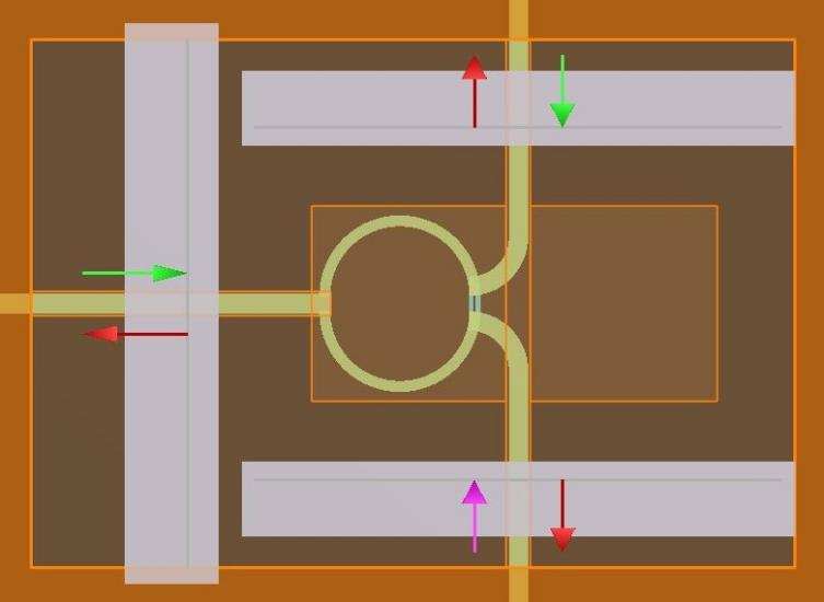
The structure group "trace and load" is used in FDTD simulation file Wilkinson_ power_ divider. The physical and electrical parameters of Wilkinson power divider are built and set in fsp. The microstrip transmission line is modeled using a two-dimensional perfect electrical conductor (PEC) rectangular plate placed on a 1.59mm thick substrate with a relative dielectric constant of 2.2. The required width of each transmission line section is calculated using equation. 3.195 and 3.197 in Pozar [1] (see microstrip.lms script file in microstrip example) are 4.9mm (Z0=50 ohms) and 2.804 mm (√ 2Z0=70.7 ohms) respectively. The quarter wavelength transmission line is constructed using 2D polygons formed into a ring. 3.194 in Pozar [1] is λ g/4=55.5 mm。 The resistor is modeled using a 2D rectangular plate that specifies a material with R=100 ohms.
The ports are placed on the input and output traces to inject the transmission line mode in the frequency range of 0.5 – 1.5 GHz and calculate the scattering parameters of the equipment. For more details on its settings, see the Ports page. As described below, the source port will be manually changed to fire one port at a time.
The mesh coverage area is placed on each track to resolve its length and width. The bending and angular properties of the branch trace require that the grid size in the x and y directions be equal (dx=dy). This is not a constraint on the feed and output tracks aligned to the coordinate axis. A copy of the mesh coverage area used for branch tracking is placed to the right of the output trace to maintain a symmetrical mesh.
The PML absorption boundary condition surrounds the entire simulation area, except for the z-minimum boundary, which is designated as the metal boundary condition simulating the grounding plane of the microstrip transmission line.
Wilkinson power divider Results and analysis
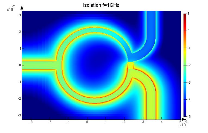
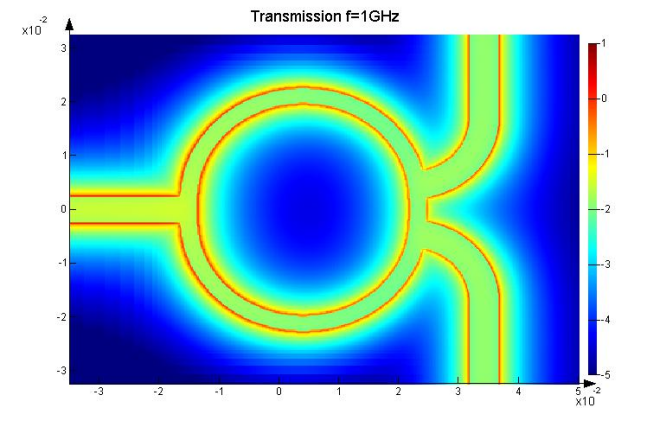
The figure above shows the frequency response of the scattering parameters used for isolation and transmission simulation and the electric field distribution at 1GHz. These numbers are generated by the script after the simulation is completed. It should be noted that these results can be obtained on the trajectory using finer meshes than those specified in the simulation file.
The analog Wilkinson power divider is well matched at its input (S11=- 40dB, f=1.0GHz) and output (S22=- 32dB, f=1GHz) ports, has good isolation (S32=- 43dB, f=1GHz), and its center frequency is 1.01GHz, which is within 1% of the design operating frequency of 1GHz. In addition, we observed 3dB equal power division (S31=- 3dB at f=1GHz) with a change of less than 10% in the analog frequency band.
Si Chuan Keenlion Microwave a large selection in narrowband and broadband configurations, covering frequencies from 0.5 to 50 GHz. They are designed to handle from 10 to 30 watts input power in a 50-ohm transmission system. Microstrip or stripline designs are utilized, and optimized for best performance.
We can also customize the Power Divider according to your requirements. You can enter the customization page to provide the specifications you need.
Sichuan Keenlion Microwave Technology Co., Ltd.
E-mail:
sales@keenlion.com
tom@keenlion.com
Post time: Dec-06-2022


