

Passive Band Pass Filters can be made by connecting together a low pass filter with a high pass filter
The Passive Band Pass Filter can be used to isolate or filter out certain frequencies that lie within a particular band or range of frequencies. The cut-off frequency or ƒc point in a simple RC passive filter can be accurately controlled using just a single resistor in series with a non-polarized capacitor, and depending upon which way around they are connected, we have seen that either a Low Pass or a High Pass filter is obtained.
One simple use for these types of passive filters is in audio amplifier applications or circuits such as in loudspeaker crossover filters or pre-amplifier tone controls. Sometimes it is necessary to only pass a certain range of frequencies that do not begin at 0Hz, (DC) or end at some upper high frequency point but are within a certain range or band of frequencies, either narrow or wide.
By connecting or “cascading” together a single Low Pass Filter circuit with a High Pass Filter circuit, we can produce another type of passive RC filter that passes a selected range or “band” of frequencies that can be either narrow or wide while attenuating all those outside of this range. This new type of passive filter arrangement produces a frequency selective filter known commonly as a Band Pass Filter or BPF for short.
Unlike the low pass filter which only pass signals of a low frequency range or the high pass filter which pass signals of a higher frequency range, a Band Pass Filters passes signals within a certain “band” or “spread” of frequencies without distorting the input signal or introducing extra noise. This band of frequencies can be any width and is commonly known as the filters Bandwidth.
Bandwidth is commonly defined as the frequency range that exists between two specified frequency cut-off points ( ƒc ), that are 3dB below the maximum centre or resonant peak while attenuating or weakening the others outside of these two points.
Then for widely spread frequencies, we can simply define the term “bandwidth”, BW as being the difference between the lower cut-off frequency ( ƒcLOWER ) and the higher cut-off frequency ( ƒcHIGHER ) points. In other words, BW = ƒH – ƒL. Clearly for a pass band filter to function correctly, the cut-off frequency of the low pass filter must be higher than the cut-off frequency for the high pass filter.
The “ideal” Band Pass Filter can also be used to isolate or filter out certain frequencies that lie within a particular band of frequencies, for example, noise cancellation. Band pass filters are known generally as second-order filters, (two-pole) because they have “two” reactive component, the capacitors, within their circuit design. One capacitor in the low pass circuit and another capacitor in the high pass circuit.
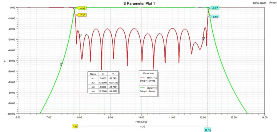
The Bode Plot or frequency response curve above shows the characteristics of the band pass filter. Here the signal is attenuated at low frequencies with the output increasing at a slope of +20dB/Decade (6dB/Octave) until the frequency reaches the “lower cut-off” point ƒL. At this frequency the output voltage is again 1/√2 = 70.7% of the input signal value or -3dB (20*log(VOUT/VIN)) of the input.
The output continues at maximum gain until it reaches the “upper cut-off” point ƒH where the output decreases at a rate of -20dB/Decade (6dB/Octave) attenuating any high frequency signals. The point of maximum output gain is generally the geometric mean of the two -3dB value between the lower and upper cut-off points and is called the “Centre Frequency” or “Resonant Peak” value ƒr. This geometric mean value is calculated as being ƒr 2 = ƒ(UPPER) x ƒ(LOWER).
A band pass filter is regarded as a second-order (two-pole) type filter because it has “two” reactive components within its circuit structure, then the phase angle will be twice that of the previously seen first-order filters, ie, 180o. The phase angle of the output signal LEADS that of the input by +90o up to the centre or resonant frequency, ƒr point were it becomes “zero” degrees (0o) or “in-phase” and then changes to LAG the input by -90o as the output frequency increases.
The upper and lower cut-off frequency points for a band pass filter can be found using the same formula as that for both the low and high pass filters, For example.
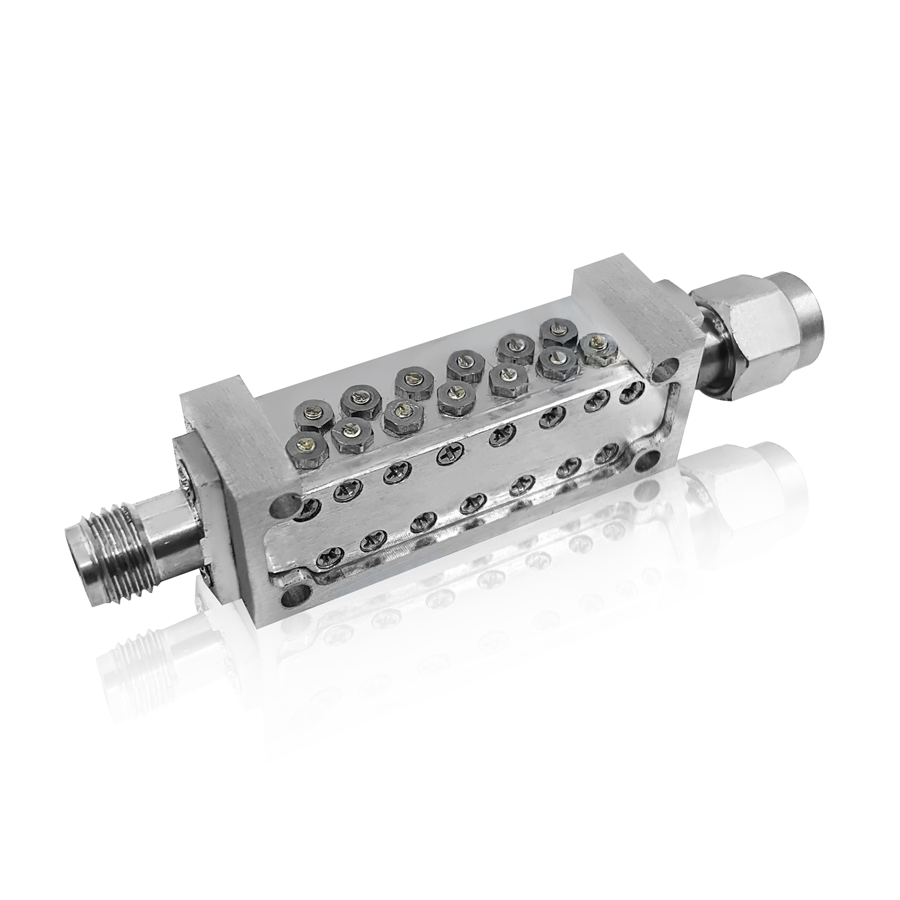
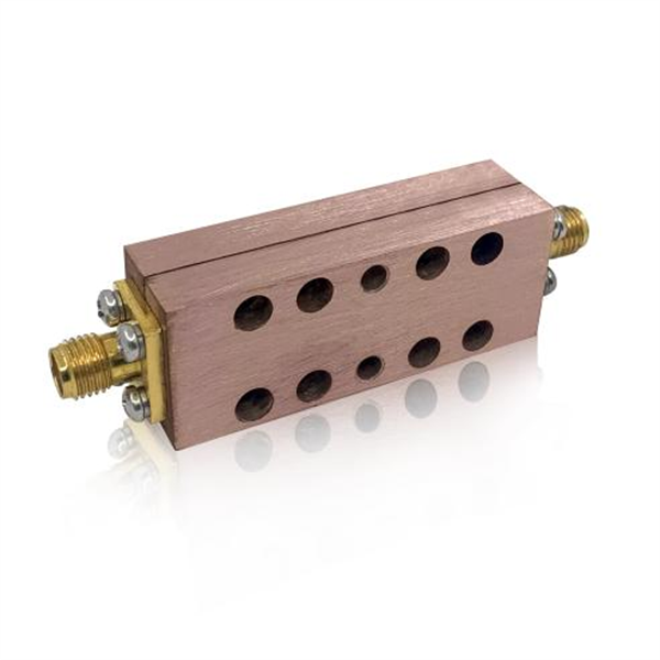
Units come standard with SMA or N female connectors, or 2.92mm, 2.40mm, and 1.85mm connectors for high frequency components.
We can also customize the Band Pass Filter according to your requirements. You can enter the customization page to provide the specifications you need.
Post time: Sep-06-2022


