

• For dividing a signal into two signals of equal amplitude and a constant 90° or 180° phase differential.
• For quadrature combining or performing summation/differential combining.
Introduction
Couplers and hybrids are devices in which two transmission lines pass close enough to each other for energy propagating on one line to couple to the other line. A 3dB 90° or 180° hybrid splits an input signal into two equal amplitude outputs. A directional coupler normally splits an input signal into two unequal amplitude outputs. This terminology “directional coupler”, “90° hybrid”, and “180° hybrid” is based on convention. However, the 90° and 180° hybrids could be thought of as 3 dB directional couplers. Despite these similarities, the parameters used to describe signal flow in directional couplers and the application, in actual use, is sufficiently different to warrant separate considerations.
180° Hybrids Functional Description
A 180° hybrid is a reciprocal four-port device which provides two equal amplitude in-phase signals when fed from its sum port (S) and two equal amplitude 180° out-of-phase signals when fed from its difference port (D). Conversely, signals input into ports C and D will add at the sum port (B) and the difference of the two signals will appear at the difference port (A). Figure 1 is a functional diagram which will be used in this article to represent the 180° hybrid. Port B can be considered the sum port and port A is the difference port. Ports A and B and ports C and D are isolated pairs of ports.
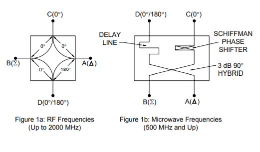
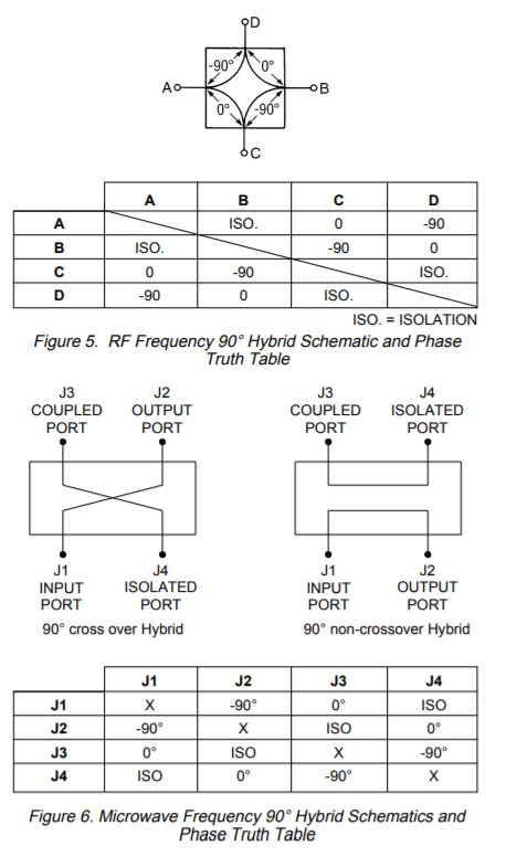
90° Hybrids or hybrid couplers are basically 3 dB directional couplers in which the phase of the coupled output signal and the output signal are 90° apart. Since -3 dB represents half power, a 3 dB coupler divides the power equally (within a certain tolerance) between the output and coupled output ports. The 90° phase difference between the outputs makes hybrids useful in the design of electronically variable attenuators, microwave mixers, modulators and many other microwave components and systems. Figure 5 shows the circuit diagram and truth table that will be used in explaining the operation of the RF frequency 90° hybrid. As can be seen from this diagram, a signal applied to any input will result in two equal amplitude signals that are quadrature, or 90°, out of phase with each other. Ports A and B and Ports C and D are isolated. As previously stated in the 180° hybrid section, the RF and microwave frequency devices employ different construction methods. Although the theoretical responses are identical, the port location and convention is different. Below, in Figure are “cross-over” and “non-crossover” versions offered for microwave frequencies (500 MHz and up) and the resulting truth table. Ninety degree hybrids are also called quadrature hybrids because the phase of the two outputs are a quadrant (90°) apart. Note also that it does not make any difference which port is the input port as long as the relationship between ports remains. This is because the 90° hybrids are electrically and mechanically symmetrical about both the X and Y Axes.
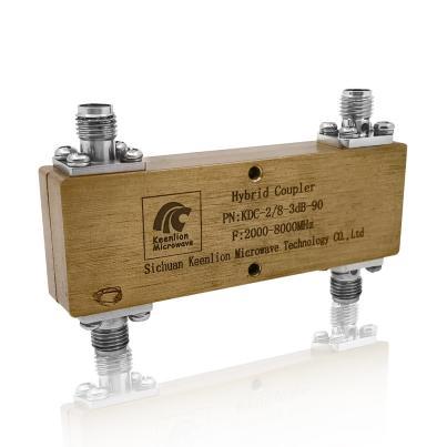
Si Chuan Keenlion Microwave a large selection of 3DB hybrid bridge in narrowband and broadband configurations, covering frequencies from 0.5 to 50 GHz. They are designed to handle from 10 to 30 watts input power in a 50-ohm transmission system. Microstrip or stripline designs are utilized, and optimized for best performance.
Units come standard with SMA or N female connectors, or 2.92mm, 2.40mm, and 1.85mm connectors for high frequency components.
We can also customize the 3DB Hybrid Bridge according to your requirements. You can enter the customization page to provide the specifications you need.
Post time: Oct-09-2022


