

Directional couplers are an important type of signal processing device. Their basic function is to sample RF signals at a predetermined degree of coupling, with high isolation between the signal ports and the sampled ports — which supports analysis, measurement and processing for many applications. Since they are passive devices, they also operate in the reverse direction, with signals injected into the main path according to the devices’ directionality and degree of coupling. There are a few variations in the configuration of directional couplers, as we shall see below.
Definitions
Ideally, a coupler would be lossless, matched and reciprocal. The basic properties of three- and four-port networks are isolation, coupling and directivity, the values of which are used to characterize the couplers. An ideal coupler has infinite directivity and isolation, along with a coupling factor selected for the intended application.
The functional diagram in Fig. 1 illustrates the operation of a directional coupler, followed by a description of the related performance parameters. The top diagram is a 4-port coupler, which includes both coupled (forward) and isolated (reverse, or reflected) ports. The lower diagram is a 3-port structure, which eliminates the isolated port. This is used in applications that only need a single forward coupled output. The 3-port coupler can be connected in the reverse direction, where the port that was formerly coupled becomes the isolated port:
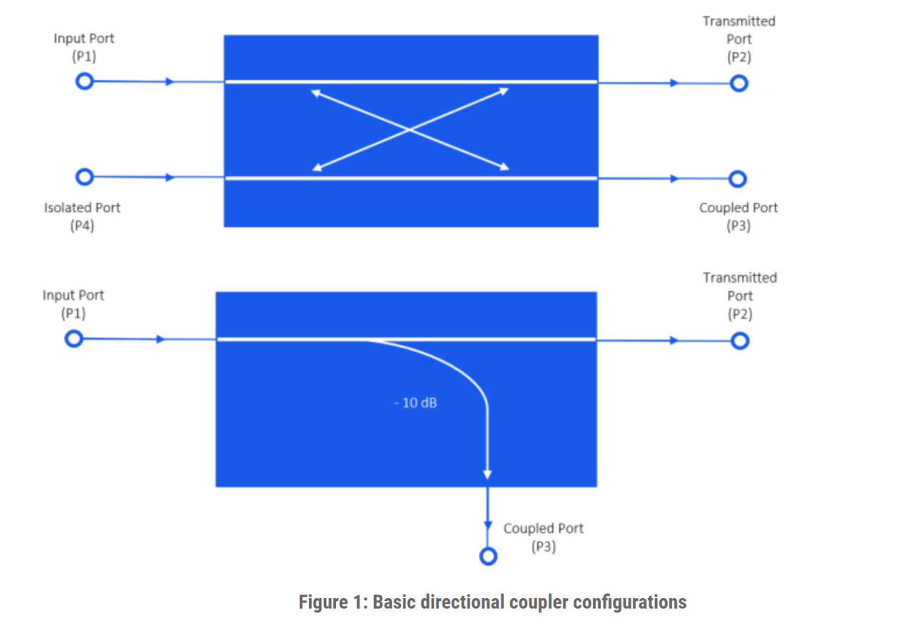
Figure 1: Basic directional coupler configurations
Performance characteristics:
Coupling Factor: This indicates the fraction of the input power (at P1) that is delivered to the coupled port, P3
Directivity: This is a measure of the coupler’s ability to separate waves propagating in forward and reverse directions, as observed at the coupled (P3) and isolated (P4) ports
Isolation: Indicates the power delivered to the uncoupled load (P4)
Insertion Loss: This accounts for the input power (P1) delivered to the transmitted (P2) port, which is reduced by power delivered to the coupled and isolated ports.
The values of these characteristics in dB are:
Coupling = C = 10 log (P1/P3)
Directivity = D = 10 log (P3/P4)
Isolation = I = 10 log (P1/P4)
Insertion Loss = L = 10 log (P1/P2)
Types of Couplers
This type of coupler has three accessible ports, as shown in Fig. 2, where the fourth port is internally terminated to provide maximum directivity. The basic function of a directional coupler is to sample the isolated (reverse) signal. A typical application is measurement of reflected power (or indirectly, VSWR). Although it can be connected in reverse, this type of coupler is not reciprocal. Since one of the coupled ports is internally terminated, only one coupled signal is available. In the forward direction (as shown), the coupled port samples the reverse wave, but if connected in the reverse direction (RF Input on the right), the coupled port would be a sample of the forward wave, reduced by the coupling factor. With this connection, the device may be used as a sampler for signal measurement, or to deliver a portion of the output signal to feedback circuitry.
Figure 2: 50-Ohm Directional Coupler
Advantages:
1、Performance can be optimized for the forward path
2、High directivity and isolation
3、The directivity of a coupler is strongly affected by the impedance match provided by the termination at the isolated port. Furnishing that termination internally ensures high performance
Disadvantages:
1、Coupling is only available on the forward path
2、No coupled line
3、The coupled port power rating is less than the input port because the power applied to the coupled port is almost entirely dissipated in the internal termination.
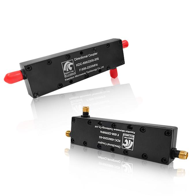
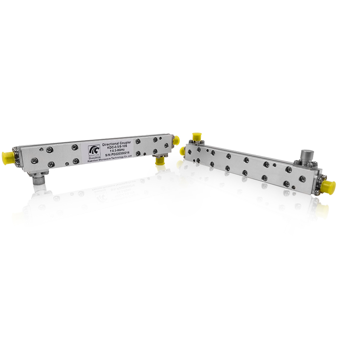
Si Chuan Keenlion Microwave a large selection of Directional Coupler in narrowband and broadband configurations, covering frequencies from 0.5 to 50 GHz. They are designed to handle from 10 to 30 watts input power in a 50-ohm transmission system. Microstrip or stripline designs are utilized, and optimized for best performance.
Units come standard with SMA or N female connectors, or 2.92mm, 2.40mm, and 1.85mm connectors for high frequency components.
We can also customize the Directional Coupler according to your requirements. You can enter the customization page to provide the specifications you need.
Post time: Aug-30-2022


